RS-422 vs RS-485: Differential Serial Compared
RS-422 is one driver to many receivers; RS-485 is a true multipoint bus. Compare distance, speed, termination and wiring, and see what damages hardware.
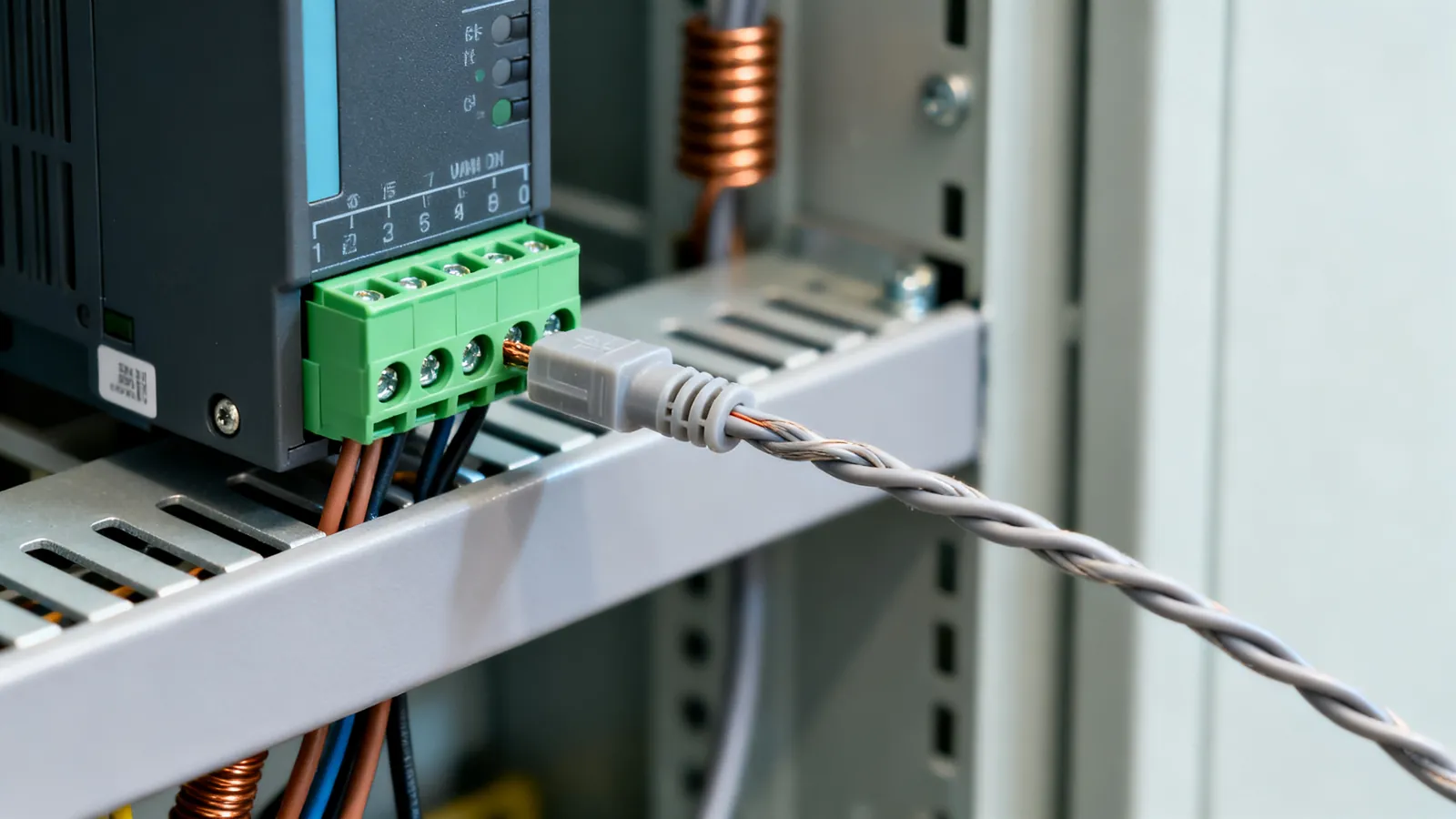
RS-422 and RS-485 are both differential serial standards, and both are still found in industrial equipment, lighting control, building systems and older lab gear. The difference that matters is topology: RS-422 is one driver feeding up to ten receivers, point to point or point to multipoint, while RS-485 is a genuine multipoint bus where up to 32 unit loads share one pair and take turns transmitting. If you are joining two devices over a long run, either can work; if you are putting several devices on one cable, you want RS-485.
Both standards are defined by EIA/TIA, and both use the same idea: instead of one wire measured against ground, the signal is the voltage difference between two wires, A and B. Noise that couples onto the cable tends to appear on both wires equally, so the difference at the receiver stays clean. That is why these standards reach far beyond the 15 m (50 ft) the single-ended RS-232 serial pinouts allow.
RS-422 and RS-485 side by side
| Property | RS-422 | RS-485 |
|---|---|---|
| Signalling | Differential | Differential |
| Drivers per pair | One | Up to 32 unit loads on one bus |
| Receivers | Up to 10 | Up to 32 unit loads |
| Duplex | Full duplex (two pairs) | Two-wire half duplex or four-wire full duplex |
| Maximum distance | 1200 m (4000 ft) at lower speeds | 1200 m (4000 ft) |
| Maximum speed | 10 Mbps at short distances | 10 Mbps at short distances |
| Termination | 120 ohm at the far end of the pair | 120 ohm at both ends of the bus |
| Typical use | Point-to-point links, encoders, scales | Modbus RTU, DMX512, multi-drop control |
RS-422 is the simpler of the two. One driver, up to ten receivers, and because it normally uses two twisted pairs it can run full duplex: data flows both ways at once. It is the natural choice for a link between two pieces of equipment over a long cable, such as a controller talking to a remote display or a motion encoder.
RS-485 keeps the differential signalling but adds the ability to put many devices on one pair. The standard counts 32 unit loads on a bus; a unit load is a defined input impedance, and transceivers rated at a fraction of a unit load let you exceed that count. Devices share the pair and take turns, which is why RS-485 is usually half duplex on two wires. Four-wire RS-485 gives full duplex on a multipoint bus, with one master transmitting on one pair and the slaves replying on the other.
Distance and speed
Both standards reach 1200 m (4000 ft) at lower speeds, and both reach 10 Mbps at short distances. The two figures are not available at once: as the data rate rises, the usable cable length falls. A 10 Mbps link is a short bench or cabinet run; a long run across a site runs at a modest baud rate. The limit is set by the rise time of the signal and by the cable, not by the driver alone.
Use twisted pair for the A and B conductors. A third conductor for signal ground is normal practice even though the signal itself is differential, because the two ends still need a common reference within the range the transceivers accept. On long runs between buildings, differences in ground potential can exceed that range, and an isolated repeater or a fiber link is the answer rather than a heavier ground wire.
RS-232 vs RS-485 in practice
The practical difference between RS-232 and RS-485 is not the voltage levels but the topology and the reach. RS-232 is single-ended, one driver to one receiver, and the standard allows 15 m (50 ft) at 19,200 baud, with lower baud rates running further. RS-485 is differential, reaches 1200 m (4000 ft), and puts many devices on one cable.
That is why so much industrial equipment uses RS-485 and so much bench equipment uses RS-232. A Modbus RTU network is RS-485: one master polls a chain of meters, drives or PLCs on a single twisted pair. A laptop connecting to a router console port is RS-232. The two are not interchangeable at the electrical level, and connecting an RS-232 port directly to an RS-485 bus will not work and can damage the transceiver. A converter is needed, and the converter must match the direction control the bus expects.
Modbus RS-485 wiring
Modbus RTU over RS-485 is the most common place people meet this standard, and most of the failures are wiring failures rather than protocol failures.
- Daisy chain, do not star. The bus runs from device to device. A star, where several cables meet at one point, creates stubs that reflect the signal. Keep any stub short.
- A and B must be consistent. Manufacturers label the pair differently, sometimes A and B, sometimes D+ and D-, sometimes plus and minus. If the bus does not respond, swapping the pair at one end is the first thing to try.
- Terminate both ends. A 120 ohm resistor across A and B at each physical end of the bus, and only there. Mid-bus devices are not terminated.
- Bias if the bus floats. When no driver is active, a terminated bus can sit at an indeterminate level and the receiver may read noise as data. Bias resistors at one point hold the idle state.
- Ground and shield. Run the signal ground with the pair, and connect the shield at one end to avoid a ground loop.
Termination and the 120 ohm rule
RS-485 termination is a 120 ohm resistor across the two signal wires at each end of the bus. The value matches the characteristic impedance of the twisted pair, so it absorbs the signal instead of letting it reflect back down the cable. Reflections arrive at the receiver as extra edges and corrupt data, and the effect gets worse as the cable gets longer and the data rate rises.
Two mistakes are common. The first is fitting terminators at every device on the bus: with several 120 ohm resistors in parallel the bus is overloaded and the signal level drops. The second is fitting none at all: short bench links often work, then fail once the cable is extended. Terminate the two physical ends and nothing in between.
RS-422 uses the same 120 ohm value, but because it is normally a single driver and receiver pair, the terminator goes at the far end of the receiving pair. Some short RS-422 links run without termination; the longer the cable, the more it matters.
Connectors and pinouts
Neither standard fixes a connector. RS-422 and RS-485 appear on DE-9 connectors, terminal blocks, RJ45 jacks, 5-pin circular connectors and proprietary plugs, and the pinout is set by the equipment maker, not by the standard. Read the manual for the device in front of you.
Where a DE-9 is used, a common RS-485 arrangement puts the pair on pins 1 and 2 or on pins 3 and 8, with ground on pin 5, but this is a convention rather than a rule. On terminal blocks the pair is usually marked A and B or D+ and D-, with a separate ground terminal. On RJ45, DMX512 lighting control uses pins 1 and 2 for the data pair and pins 7 and 8 for a second pair, again by convention.
Because the pinout is not standardised, a cable that works between two devices of one make may not work between two of another. Label both ends and keep a note of the pinout used.
Getting a PC onto an RS-485 bus
Most computers no longer have a serial port, so the link is usually a USB adapter. A USB-to-RS-485 adapter contains a converter chip and a transceiver, and it needs the right driver. The pitfalls are the same as for other serial adapters: counterfeit converter chips can be blocked by the genuine maker’s drivers, and an adapter with TTL output is not an RS-485 interface at all. The same rules apply as for USB to serial adapters in general, with the added point that an RS-485 adapter must handle the transmit direction control, either automatically or through a handshake line.
What goes wrong
- Mixing standards. RS-232, RS-422 and RS-485 are not interchangeable. Feeding an RS-232 port into an RS-485 bus, or the reverse, can damage the transceiver on the low-voltage side. Use a proper converter.
- HVD on a low-voltage bus. High voltage differential devices must never be connected to a single-ended or low voltage differential bus. The mismatch can destroy the transceivers.
- Star wiring. A bus is a chain. Branches and stubs cause reflections that appear as intermittent errors, often only on long cables or at higher baud rates.
- Wrong termination. Terminators at every device overload the bus; no terminators at the ends leave reflections. Both produce errors that look like protocol faults.
- A and B swapped. The bus is silent. Swap the pair at one end.
- No ground reference. The differential pair still needs a common reference within the transceiver’s range. Without it, long runs between buildings fail, and ground potential differences can damage the ports.
- Untwisted cable. Parallel conductors pick up noise differently on each wire, which defeats the whole point of differential signalling. Use twisted pair.
- Too many unit loads. More than 32 standard unit loads on one bus, or a mix of full and fractional loads that adds up past the limit, overloads the drivers.
Choosing between them
For a link between two devices over a long cable, RS-422 is the straightforward answer: one driver, up to ten receivers, full duplex on two pairs, terminated at the far end. For a network of devices on one cable, RS-485 is the answer: a daisy-chained twisted pair, 120 ohm terminators at both ends, a signal ground, and a protocol such as Modbus RTU or DMX512 to keep the traffic orderly. Both reach 1200 m (4000 ft) at lower speeds and 10 Mbps at short distances, and both depend far more on correct wiring than on the transceivers themselves.
Common questions
Can I connect an RS-422 device to an RS-485 bus?
Sometimes, but not by assuming they match. RS-422 is one driver to many receivers; RS-485 is a shared bus where devices take turns. A four-wire RS-485 bus is electrically close to RS-422, but the direction control and the number of drivers differ. Check the transceivers in both devices before joining them.
How do I terminate an RS-485 bus?
Fit a 120 ohm resistor across the two signal wires at each physical end of the bus, and nowhere else. Mid-bus devices are left unterminated. Terminators at every device put several resistors in parallel, overload the bus and reduce the signal level.
How far can RS-485 run?
Up to 1200 m (4000 ft) at lower speeds, and up to 10 Mbps at short distances. The two are not available at once: as the data rate rises, the usable length falls. Use twisted pair and keep the bus a daisy chain rather than a star.
What is the difference between RS-232 and RS-485?
RS-232 is single-ended, one driver to one receiver, and the standard allows 15 m (50 ft) at 19,200 baud. RS-485 is differential, reaches 1200 m (4000 ft) and puts up to 32 unit loads on one bus. They are not electrically compatible and need a converter between them.
Why does my Modbus RS-485 network work on the bench but fail on site?
The usual causes are star wiring with long stubs, missing or duplicated terminators, a swapped A and B pair, or no signal ground between the ends. All of these show up as intermittent errors that get worse as the cable gets longer or the baud rate rises.
Read next
RS-232 Pinouts: DB9 and DB25 Explained
Complete RS-232 pinout reference for DB9 and DB25 connectors: DTE and DCE pin assignments, voltage levels, cable limits, and the TTL mistake that damages boards.
Null Modem Cables: Wiring, Adapters and Pinouts
A null modem cable crosses TX and RX to join two computers directly. Covers DB9 and DB25 pinouts, adapters versus cables, gender changers and loopback testing.
SCSI Cables, Connectors and Terminators
SCSI cable types explained: 50-pin, HD68 and SCA-80 connectors, narrow vs wide buses, SE, LVD and HVD signalling, termination rules and length limits.