RS-232 Pinouts: DB9 and DB25 Explained
Complete RS-232 pinout reference for DB9 and DB25 connectors: DTE and DCE pin assignments, voltage levels, cable limits, and the TTL mistake that damages boards.
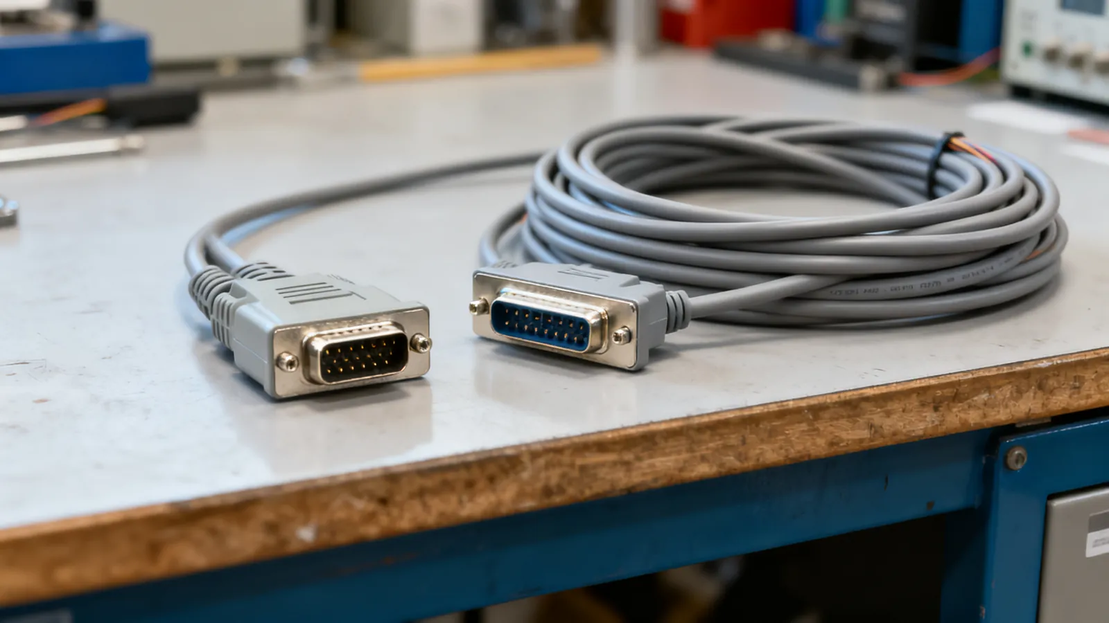
RS-232 serial ports still run point-of-sale terminals, industrial controllers, network switches, lab instruments and older computers. The connector on the back is usually a DE-9 (commonly called DB9) or a DB25, and the pinout depends on whether the device is wired as DTE or DCE. Get that wrong and the link simply will not work; connect RS-232 to a low-voltage TTL header and you can destroy the board.
The DB9 pinout
The DE-9 connector has nine pins in two rows. The standard PC (DTE) pinout is:
| Pin | Signal | Direction (DTE) | Purpose |
|---|---|---|---|
| 1 | DCD | Input | Data carrier detect |
| 2 | RXD | Input | Received data |
| 3 | TXD | Output | Transmitted data |
| 4 | DTR | Output | Data terminal ready |
| 5 | GND | — | Signal ground |
| 6 | DSR | Input | Data set ready |
| 7 | RTS | Output | Request to send |
| 8 | CTS | Input | Clear to send |
| 9 | RI | Input | Ring indicator |
Pin 5 is the signal ground and is always required. Pins 2 and 3 carry the data: TXD is the output from the computer, RXD is the input to it. The remaining pins are handshaking and modem control lines. A minimal link needs only pins 2, 3 and 5, but many devices wait for DSR or CTS before they will transmit.
The DB25 pinout
The DB25 uses 25 pins and was the original RS-232 connector on IBM PCs and many modems. The DTE pinout is:
| Pin | Signal | Direction (DTE) |
|---|---|---|
| 2 | TXD | Output |
| 3 | RXD | Input |
| 4 | RTS | Output |
| 5 | CTS | Input |
| 6 | DSR | Input |
| 7 | GND | — |
| 8 | DCD | Input |
| 20 | DTR | Output |
| 22 | RI | Input |
Pins 1 and 9 through 19 are mostly unused or reserved. The important difference from the DB9 is that TXD and RXD sit on pins 2 and 3 in both connectors, but the handshake lines move: DTR is pin 20 on the DB25 and pin 4 on the DB9, while DSR is pin 6 on both. A DB9-to-DB25 adapter must map these correctly, and not every cheap adapter does.
DTE and DCE: which end is which
DTE means data terminal equipment: a computer, terminal or controller. DCE means data communications equipment: a modem, or a device that behaves like one. The pinout above is the DTE view. On a DCE device, TXD and RXD swap, and so do the handshake pairs.
A straight-through cable joins a DTE to a DCE. To join two DTEs, such as two computers, you need a null modem cable or adapter that crosses TXD and RXD, crosses RTS and CTS, and crosses DTR to DSR and DCD. Signal ground runs straight through. A gender changer only swaps male and female shells; it crosses nothing.
RS-232 voltage levels
RS-232 is single-ended and uses inverted logic at higher voltages than modern digital circuits. A voltage between +3 V and +15 V is a logic 0 (space). A voltage between -3 V and -15 V is a logic 1 (mark). The region between -3 V and +3 V is undefined and is treated as noise.
Those levels are what make RS-232 robust over cable but incompatible with microcontroller pins. A TTL or CMOS serial port runs at 3.3 V or 5 V and is not RS-232. Joining the two directly can damage the low-voltage side. A level shifter or a USB-to-TTL adapter is needed, and adapters with TTL output are not RS-232. See USB to serial adapters: drivers, levels and pitfalls for the converter chips and driver problems that come with them.
How far RS-232 runs
The standard allows up to 15 m (50 ft) at 19,200 baud. Lower baud rates run further. The limit is set by cable capacitance, not by the driver, so a low-capacitance cable can stretch the distance and a long coiled cord will not. For runs beyond that, or for multiple drops on one line, RS-422 and RS-485 are the differential alternatives; the differences are covered in RS-422 vs RS-485.
What goes wrong
TTL on an RS-232 port. The most expensive mistake. A 3.3 V or 5 V microcontroller header connected to a real RS-232 port sees voltages far outside its supply range. The low-voltage side can be damaged. Always check whether a port is RS-232 or TTL before connecting.
Wrong cable type. A straight-through cable between two DTEs will not pass data. A null modem cable between a DTE and a DCE will not either. If a link does nothing, the cable is the first thing to check.
Missing ground. Pins 2 and 3 alone are not enough if the two devices have no common ground reference. Pin 5 (DB9) or pin 7 (DB25) must be connected.
Handshake lines ignored. Some devices assert DTR or RTS and wait for DSR or CTS before sending. A three-wire cable will appear dead. Loopback jumpers at the connector can satisfy the device, but they must be fitted at the correct end.
Counterfeit adapter chips. USB-to-serial adapters contain a converter chip that needs the right driver. Counterfeit chips can be blocked by the genuine maker’s drivers, leaving the adapter unusable after a driver update.
DB9 and DB25 mixed up. The two connectors use different pin numbers for the same signals. A passive adapter that only changes the shell shape will not work unless it also remaps the pins.
Choosing and checking a serial cable
Match the connector at each end, then match the wiring. If both ends are DTE, use a null modem cable. If one end is DCE, use a straight-through cable. If the device is unknown, a breakout box or a continuity tester will show which pins are connected and which cross.
For new installations, a USB-to-serial adapter with the correct driver is usually simpler than finding a PC with a real port. For equipment that must keep its original connector, a correctly wired DB9 or DB25 cable is still the right answer. Label both ends, and keep a note of the pinout used, because a cable that works on one device may be wired differently from the next.
Common questions
What is the DB9 pinout for RS-232?
On a DTE device: pin 1 DCD, pin 2 RXD, pin 3 TXD, pin 4 DTR, pin 5 signal ground, pin 6 DSR, pin 7 RTS, pin 8 CTS, pin 9 RI. Pins 2, 3 and 5 are the minimum for data.
What is the DB25 pinout for RS-232?
On a DTE device: pin 2 TXD, pin 3 RXD, pin 4 RTS, pin 5 CTS, pin 6 DSR, pin 7 signal ground, pin 8 DCD, pin 20 DTR, pin 22 RI. Pins 1 and 9 through 19 are mostly unused.
What are RS-232 voltage levels?
A voltage between +3 V and +15 V is a logic 0 (space). A voltage between -3 V and -15 V is a logic 1 (mark). The region between -3 V and +3 V is undefined.
How far can RS-232 run?
The standard allows up to 15 m (50 ft) at 19,200 baud. Lower baud rates run further. The limit is set by cable capacitance, so a low-capacitance cable can stretch the distance.
Can I connect RS-232 directly to a microcontroller?
No. RS-232 uses voltages up to +15 V and -15 V, while TTL and CMOS serial ports run at 3.3 V or 5 V. Joining them directly can damage the low-voltage side. Use a level shifter or a USB-to-TTL adapter.
Read next
Null Modem Cables: Wiring, Adapters and Pinouts
A null modem cable crosses TX and RX to join two computers directly. Covers DB9 and DB25 pinouts, adapters versus cables, gender changers and loopback testing.
SCSI Cables, Connectors and Terminators
SCSI cable types explained: 50-pin, HD68 and SCA-80 connectors, narrow vs wide buses, SE, LVD and HVD signalling, termination rules and length limits.
RS-422 vs RS-485: Differential Serial Compared
RS-422 is one driver to many receivers; RS-485 is a true multipoint bus. Compare distance, speed, termination and wiring, and see what damages hardware.